


What is an engine?
An engine is a mechanism or moving system that extracts energy from fuel and turns it into motion. An engine's input is any type of fuel (petrol, diesel, coal, CNG, etc.), and its output is the resulting motion obtained after processing the fuel.
The engine is the heart of any automobile system since it gives power to the entire vehicle. Engines can be argued to be a need in our daily lives.
Automobile engines play a critical role in our daily lives. It has simplified transportation, linking people all over the world.
Now we shall look at the classification of many types of engines.
The different types of engines are determined by the following factors. Fuel types utilized Number of strokes Number of cylinders in the ignition system Types of Cooling Cycle Operation Valve and cylinder placement, for example. We shall investigate each one in depth.
Different Types of Engines:
There are mainly two types of Engine:
- External combustion engine and
- Internal combustion engine
External combustion engine:
Because the external combustion engine was invented in 1816 by a Scottish engineer named Robert Stirling, these engines are commonly referred to as Stirling engines.
From 1818 to 1922, Robert's firm produced these engines. Because of their enormous capacity and great power output, external combustion engines were commonly utilized in locomotives.
External combustion engines, however, became obsolete over time since they required a lot of effort to run.
An external combustion engine, as the name implies, burns the fuel independently in a combustion chamber and uses the heat generated to raise the temperature of the working gas.
External combustion engine Construction:
The basic construction of an external combustion engine involves only three different arrangements.
- Combustion chamber
- Boiler and
- Piston cylinder arrangement
Combustion chamber:
In an external combustion engine, the combustion chamber provides heat. The combustion chamber can burn fuel either manually or mechanically.
The fuel utilized might be of various forms, but in general, an external combustion engine employs coal as fuel due to its ability to burn for an extended period of time. Although burning the charge is a difficult and time-consuming task.
Boiler:
A boiler is the section of an external combustion engine that retains the working fluid, which is typically water. The combustion chamber inside the boiler heats the water and converts it to steam. The boiler's primary job is to transform water into steam.
Piston cylinder arrangement:
The piston-cylinder configuration is employed to propel the entire vehicle. The piston moves in response to the supply of steam inside the cylinder.
The piston is then attached to the crank mechanism, which converts the reciprocating action to rotating motion.
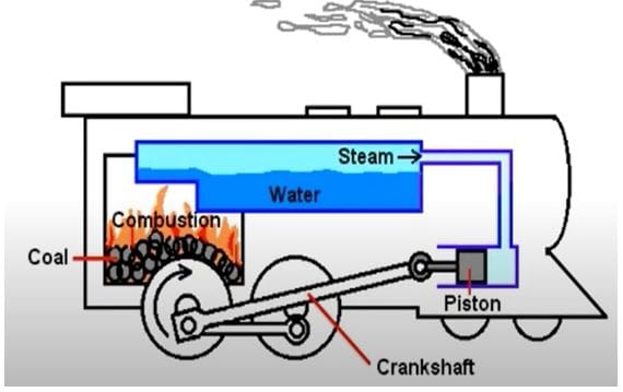
Working of the external combustion engine:
- At first the operator ignites some charge in the combustion chamber of the engine.
- The operator has to wait for the water to reach its boiling point.
- As soon as the water reaches its boiling point the pressure starts building inside the piston-cylinder arrangement and the driver starts the engine.
- This results in the movement of the locomotive.
Why did the external combustion engine fail?
There are many reasons why an external combustion engine could not survive with growing technology.
- These engines cause a lot of noise which results in increased noise pollution.
- It is also responsible for air pollution as it emits a high amount of emission gases.
- It also consumes a lot of fuel and has a large size.
- Another disadvantage is that the engine takes time to start.
Internal combustion engine:
The internal combustion engine is a type of engine in which fuel is burned inside a piston-cylinder configuration. The internal combustion engine (IC) replaced the previous external combustion engine because it is smaller, more economical, and creates less noise and pollution. Except for locomotives, IC engines are ideal for any automobile.
History of the internal combustion engine:
The internal combustion engine has a long history. Robert Street invented the first patented internal combustion engine in 1794; it was the first engine to use liquid fuel. In 1798, John Stevens created the first American engine.
In 1808 De Rivas created the first internal combustion car prototype. George Baryton invented the first commercial liquid-fueled internal combustion engine in 1872.
Now we will look at various types of Internal combustion Engines depending on various parameters.
#1. Based on the number of strokes:
Engines can be classified based on the number of strokes the piston travels from TDC to BDC of the engine. There are two types of engines based on the number of strokes.
- Four-stroke engines and
- Two-stroke engines
Four-stroke engines:
A four-stroke engine completes a cycle in four strokes. Suction, compression, power, and exhaust stroke are the four strokes. It is the most often utilized engine today. The majority of the cars have four-stroke engines.
Construction of a four-stroke engine:
The figure below shows the basic diagram of a four-stroke engine.
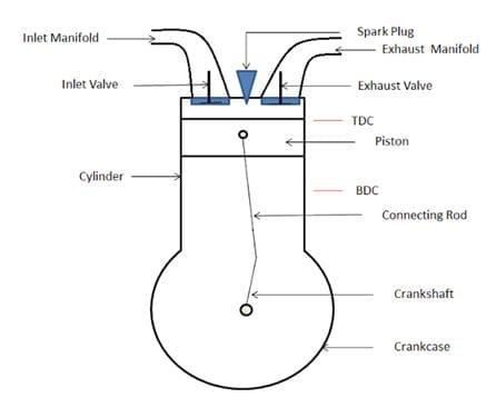
- The four-stroke engine consists of an inlet valve to control the inlet of fuel. There is an exhaust valve for the exhaust gases to vent out.
- The engine consists of a piston-cylinder arrangement. The piston is connected to the crankshaft by a connecting rod.
- TDC and BDC indicate top dead center and bottom dead center respectively.
- The distance between TDC and BDC is called one stroke of the engine.
- The exhaust and inlet manifold are the ways for the charge to come in and for the exhaust gases to vent out respectively.
Different strokes of a four-stroke engine are explained below.
Suction stroke:
The suction stroke is the first of the four-stroke engine's strokes. As the piston advances from TDC to BDC, a suction or vacuum is created. At this point, the engine's inlet valve is open, allowing the charge (a mixture of air and fuel) to enter the cylinder.
The charge is loaded into the cylinder arrangement as the piston travels towards BDC. The suction stroke allows the charge to enter the cylinder.
Compression stroke:
When the suction stroke reaches BDC, the compression stroke begins. The piston advances toward the BDC, compressing the charge. They charge the fluid by compressing it, causing the volume to decrease and the pressure to rise.
As a result, energy is stored in the charge. When the piston reaches top dead center, the compression stroke is complete.
Power stroke:
The third and most essential stroke is the power stroke. This stroke, as the name implies, provides power to the vehicle. It is often referred to as the working stroke.
When the piston is at TDC, the power stroke begins. The fuel ignites and forces the piston back to BDC with great force. The piston receives energy from the fuel that is burned. When the piston reaches BDC, the power stroke is over.
Exhaust stroke:
The exhaust stroke is the last stroke of a four-stroke engine. When the fuel is burnt it produces some emissions in the form of gases that are rich in carbon content.
These gases need to be removed from the cylinder. Hence the piston moves from BDC to TDC to push the exhaust gases out of the exhaust valve. At this time the exhaust valve is kept open.
Two-stroke engine:
The engine which completes its cycle in 2 strokes is called a two-way stroke engine. These types of engines were used in old vehicles such as Yamaha RX-100, Kinetic Honda, Bajaj Chetak, etc. There is no power in each cycle of a 2 stroke engine.
Construction of a two-stroke engine:
The figure below shows the basic diagram of a two-stroke engine.
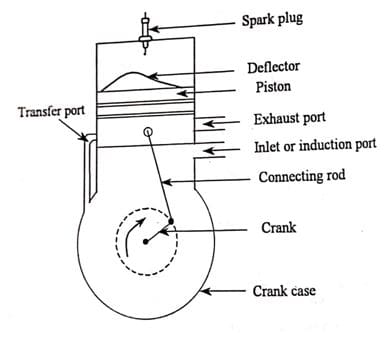
- Instead of exhaust and inlet valves, there are exhaust and inlet ports in a two-stroke engine. The ports are controlled by the movement of the piston itself.
- The piston is attached to the crank with the help of a connecting rod similar to that of the four-stroke engine.
- The two-stroke engine is provided with a transfer port that transfers the fuel from the crankcase to the volume above the piston.
- The piston is also provided with a deflector which helps the emission of exhaust gases by deflecting their path.
The two strokes involved in a two-stroke engine are:
First stroke:
During the first stroke, the piston is at TDC and the inlet port is open. The charge from the inlet port enters the cylinder and goes into the crankcase. When the piston moves down from TDC towards BDC the piston covers the inlet port and uncovers the exhaust port.
This happens around 80 percent of the first stroke. At this time the crank mechanism pushes the fuel from the crankcase to the transfer port.
Hence in the first stroke the fuel comes in, the exhaust gases go out and the fuel reaches the transfer port.
Second stroke:
In the second stroke, the piston is at BDC. This pushes the charge to come up towards the burning area. There is a minor loss of charge through the exhaust port of the engine. The engine starts moving towards TDC from BDC.
This pushes the charge, which develops pressure on the charge. The fuel is then ignited and the Energy stored in the fuel is released. The release of energy results in the power stroke of the two-stroke engine. And the process continues.
Comparison between Two-stroke and Four-stroke engines:
| Sr No. | Description | Two-stroke Engine | Four-stroke Engine |
| 1. | Completion of cycle | On completion of two strokes of the piston, the cycle is completed. | On completion of four strokes of the piston, the cycle is completed. |
| 2. | Power stroke | Every one revolution | Every two revolutions |
| 3. | Weight | Light | Heavy |
| 4. | Valves | In this inlet and exhaust valves are present which are operated by a cam mechanism | In this ports are present which open and close by piston movement |
| 5. | Size of flywheel | A lighter flywheel is employed because the turning moment produced is uniform | Heavy flywheel is employed because the turning moment is not uniform |
| 6. | Noise level | High | Less |
| 7. | Cost | Less expensive | More expensive |
| 8. | Output | Gives less output because fresh charge mixes with the burnt gases | Gives more output than two-stroke because intake of fresh air charge is maximum and exhaust gases are burnt completely |
| 9. | Fuel consumption | More fuel consumption | Less fuel consumption |
| 10. | Lubrication | Consumes more lubricating oil | Consumes less lubricating oil |
#2. Engines based on the cycle of operation:
There are 3 types of air standard cycles on which the engines are based. The air standard cycles are the closed cycles where the working fluid is the air that reassembles the actual open cycle.
- Otto cycle
- Diesel cycle and
- Dual cycle
There are some assumptions made before dealing with the air standard cycles.
- The working fluid in the cylinder is air.
- As the air behaves like an ideal gas the specific heat is constant for all temperatures.
- The mass of the medium is taken to be constant.
- The friction is neglected and unintentional heat losses are also neglected.
- The heat energy added to the medium is from the heat reservoir.
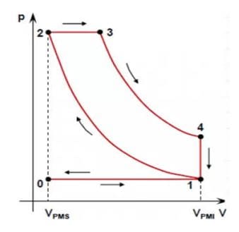
Otto cycle:
The otto cycle comprises one constant pressure, two constant volumes, and two reversible adiabatic processes. The P-V diagram of the otto cycle is given below.
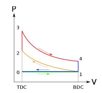
Process (0-1):-
Process0-1 indicates a constant pressure process in which the piston moves from TDC to BDC. Here the fuel is air so the air is taken in. This process is a constant pressure process.
Process (1-2):-
Process 1-2 indicates a reversible adiabatic process in which the air is compressed in an adiabatic volume. The pressure is increased and the volume is decreased.
Process (2-3):-
Process 2-3 is a constant volume process in which the working fluid that is air is ignited at a constant volume. During this process, the volume remains constant and the pressure increases which increases the temperature.
Process (3-4):-
In this process, the air expands adiabatically which pushes the piston towards BDC thus increasing the volume and releasing the pressure. It indicates the power stroke of the engine.
Process (4-1):-
Process 4-1 is again a constant volume process in which the heat is released in a constant volume. And the engine comes back to its original state.
Process (1-0):-
This process indicates the exhaust action of the IC engine where the exhaust valve is open and the air is vented out keeping the pressure constant.
Diesel cycle:
The air standard cycle for a diesel engine consists of two constant pressure processes, two adiabatic processes, one constant volume process.
Process (0-1):
This process is a constant pressure process where the air comes inside the combustion chamber. The inlet valve is open at this time due to which the pressure remains constant.
Process (1-2):
The process from 1-2 is an adiabatic compression where the air is compressed to high pressure. The volume is also reduced by the piston.
Process (2-3):
Once the air or the charge is compressed it reaches its ignition temperature. The charge is allowed to ignite at a constant pressure.
Process (3-4):
Process 3-4 is again an adiabatic expansion. In this, the piston moves downwards due to the force generated by the burning of fuel.
Dual air cycle:
The dual air standard cycle is a combination of the otto cycle and the diesel cycle. This was developed because the combustion in otto does not take place at constant volume and the combustion in diesel cycles does not take place in constant pressure.
The diagram of the dual air cycle is given below.
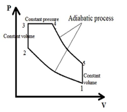
This cycle consists of
- Process (1-2): adiabatic compression
- (2-3): constant volume process
- (3-4): constant pressure process
- (4-5): adiabatic expansion and
- (5-1): constant volume process
#3. Engines based on the type of ignition:
Ignition is the process of burning fuel by creating a temperature higher than the ignition point of any fuel. Ignition of fuel is an extremely important factor that decides the performance of any engine. The proper ignition of fuel determines the quality of power stroke in the engine.
Based on the type of ignition there are two types of engines.
- Spark ignition
- Compression ignition
Spark ignition engine:
The spark-ignition engines are used by fuels having low inflammability such as petrol, LPG, methanol, hydrogen, etc. The spark-ignition engine uses a spark plug to ignite the fuel.
The spark plugs are generally situated on the top of the cylinder. The charge here is the mixture of fuel and air. This type of engine requires a carburetor for the inlet of air and fuel mixture.
The basic construction of a spark-ignition engine.
The picture of the basic parts involved in the spark-ignition engine is given below.
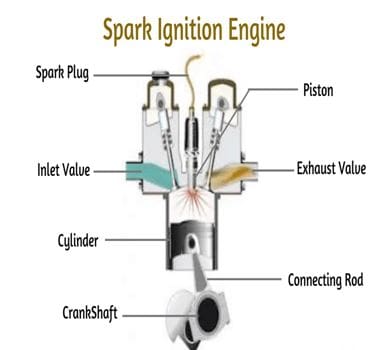
The SI engine is provided with a spark plug which provides a spark for a very short duration of time; this spark generates a temperature enough to burn the fuel. The inlet manifolds of SI engines are connected to the carburetor for the inlet of the air-fuel mixture. The process of fuel combustion takes place at constant volume hence it works on the otto cycle.
Working of spark ignition engine:
The fuel and air mixture enters the cylinder via the carburetor during the suction phase.
When the piston compresses the fuel and the piston reaches TDC. The spark plug creates a spark that ignites the fuel.
This results in the expansion or power stroke followed by the exhaust stroke.
Compression ignition engine:
The compression ignition engines or CI engines are used by fuels such as diesel. As the name suggests, in compression ignition engines the fuel is burnt due to the heat of compression. There is no carburetor or spark plug, but instead, a fuel injector is used. These engines burn fuel at constant pressure hence they work on the diesel cycle.
The basic construction of a compression ignition engine:
The figure below shows the basic construction of a CI engine
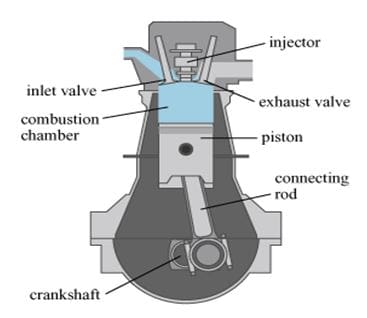
The compression ignition engines consist of a fuel injector installed on the top and the spark plug is absent. The inlet valve supplies only air and the carburetor is not present before the inlet manifold. The fuel is ignited with the compression force exerted by the piston.
Working of compression ignition engines:
During the suction stroke, only air-filtered air enters the engine via the inlet valve. And the piston reaches BDC.
After the suction stroke, the piston moves towards the TDC and compresses the air present inside the cylinder.
When the piston reaches TDC the fuel is injected. The fuel gets ignited due to high pressure and temperature between the piston and the cylinder.
Comparison between SI and CI engines:
| Sr No. | Description | S.I Engine | C.I Engine |
| 1. | Cycle | It works on the Otto cycle | It works on the Diesel cycle |
| 2. | Mixtures | The mixture of fuel and air is injected into the cylinder | Only fuel is injected into the cylinder. |
| 3. | Fuel used | Gasoline or petrol is used | Diesel is used |
| 4. | Weight | Due to low-pressure development, it weighs less | Due to high-pressure development, it weighs heavy |
| 5. | Use of carburetor | A carburetor is used to prepare the uniform mixture of air and fuel which is then supplied to the cylinder | The carburetor is not used here because fuel is provided by means of a fuel pump |
| 6. | Ignition | Spark plugs are used for ignition | The temperature rises because of high compression of air due to which self-ignition takes place |
| 7. | Starting | Starting is easy because the amount of cranking effort required is less | Starting is difficult because the amount of cranking effort required is more. |
| 8. | Noise level | Noise level is low in S.I engine due to low compression ratios | Noise level is high in C. I engine due to high compression ratios. |
| 9. | Vibrations produced | Low | High |
| 10. | Speed | Operates at a high rpm. The speed range is 3000-6000 rpm. | Operates at a lower rpm than the S.I engine. The speed range is 400-3500 rpm. |
#4. Engine based on number of cylinders:
The number of cylinders in an engine represents the number of piston-cylinder arrangements. The Greater the number of cylinders, the higher will be the power output of the engine.
This is because every cylinder produces its own energy which is then multiplied by the number of cylinders.
Based on the number of cylinders there are two types of engines.
- Single-cylinder engines
- Multi-cylinder engines
Single-cylinder engines:
A single-cylinder engine consists of one combustion chamber with one piston-cylinder arrangement. The power output for a single-cylinder engine is quite low hence it is used for very small vehicles and radio-controlled vehicles.
These engines are also called thumper engines. Other than vehicles, these engines are also used in lawnmowers and gardening machinery.
Multi-cylinder engines:
Multi-cylinder engines are IC engines with multiple piston-cylinder arrangements. These produce higher power when compared to the single-cylinder engine.
Most of the automobiles right from two-wheelers to heavy industrial vehicles use multi-cylinder engines. With the increase in the number of cylinders the power output increases but it also decreases the economy of the vehicle.
#5. Engines are based on the arrangement of cylinders:
The arrangement of cylinders is also a very important aspect of any engine. Arrangement of cylinders affects the overall weight, height, area, and other configurations of any engine including the Power of the engine.
There are a variety of arrangements of cylinders in an engine that are used for various applications. Some of the engines based on the arrangement of cylinders are given below.
- Inline engines
- V engines
- Radial engines
- Opposed cylinder engines
- Opposed piston engines
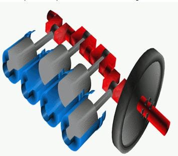
In-line engines:
In-line engines are one of the most popular engine types used in the automobile industry. These engines are designed in a way that the cylinder coincides with each other linearly. All these cylinders transmit Power to a single crankshaft.
In-line engines with four or six cylinders are the most widely used ones. The design of such engines is simple. They are also quite cost-efficient.
These engines may cause some vibrations due to the design and are often used in economic cars. The power output is not sufficient enough for muscle cars.
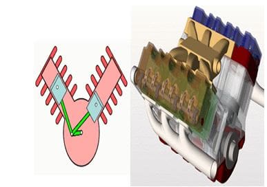
V engines:
As the name suggests a V engine has cylinders arranged in V shape. This reduces the weight of the engine and also makes it compact. These types of engines use a single crankshaft which is run by two pistons. The angle between the two banks of the V engines is known as the bank angle.
Engines having more than 6 cylinders uses the V arrangement to produce high Powe output. These engines are used where the power output requirement is more.
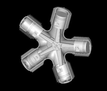
Radial engines:
In a radial engine, the cylinders are arranged radially which is used to operate a single crankshaft. These types of engines were commonly used in aircraft till the gas turbine became common. In some of the aircraft, the engines with 3, 5, or 7 cylinders were mostly used.
Opposed cylinder engines:
An opposed cylinder engine is designed in such a way that the piston head faces opposite to each other. The two pistons operate a single crankshaft. In these engines when one piston reaches TDC the other reaches BDC. These engines are generally used in small-screen aircraft and have limited applications.
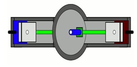
Opposed piston:
Opposed piston engines are a special type of engine with only one cylinder but two pistons. These pistons operate two separate crankshafts. It is a well-balanced engine with no cylinder head. These engines are two-stroke engines with ports instead of valves. The fuel used is generally diesel.
#6. Engines based on the type of fuel used:
Fuel is a substance that holds the energy to run an engine. When fuel is burnt the energy is released which is then used by the engine to obtain useful work.
Hence we can say that the substance which provides energy to the engine is known as fuel. There are a variety of fuels used in an IC engine and according to which the engines are designed.
The different types of fuels used in IC engines are as follows.
- Petrol or gasoline engines
- Diesel engines
- CNG engines and
- LPG engines
Petrol or gasoline engines:
Petrol or gasoline is the most commonly used fuel in automobiles and it also produces less pollution. Most of the personal vehicles including bikes and small cars run on petrol. Petrol is extracted by the fractional distillation of the crude oil which is obtained generally from the sea bed.
Properties of petrol:
- Flashpoint = – 45o C
- Autoignition temperature = 280oC
- Physical state = liquid
- Odor = has natural Odour
- Density = 0.73 kg/L approx
Petrol ignites at high temperatures therefore the petrol engines are always spark-ignition engines. In petrol engines, the fuel is mixed with air in the carburetor and then released in the cylinder through the intake manifold. But in modern automobiles, petrol is injected through the fuel injector.
Diesel engines:
Diesel is another important fuel that is generally used in heavy automobiles where power is an important factor. It is also a bi-product obtained by the fractional distillation of crude oil. Diesel produces more pollution than petrol but is cheap.
Properties of diesel:
- Flashpoint > 52oC
- Autoignition temperature = 210oC
- Physical state = liquid
- Odor = has natural Odour
- Density = 0.85 Kg/L
Diesel has a low autoignition temperature, hence it does not require a spark plug to get ignited. Diesel is ignited by creating high pressure which in turn raises the temperature enough to ignite the fuel.
Therefore the engines that use diesel as a fuel are compression ignition engines. The fuel comes in by the fuel injector and the air enters through the intake manifold.
CNG engines:
CNG stands for compressed naturalization gas. These are made by compressing natural gas like methane to 1% of its volume. CNG is a low polluting fuel that can be used as a substitute for gasoline. The power output of CNG is low when compared to petrol or diesel.
Properties of CNG
- Flashpoint = -188oC
- Autoignition temperature = 537oC
- Physical state = gaseous
- Odor = Odourless but a smell is added to detect the leakage
- Density = 0.8 kg/mm3
CNG engines are same as the petrol engines. It can be used as an alternate fuel for petrol engines. The CNG engines are used in an auto rickshaw for better efficiency. In the CNG petrol IC engine, the engine starts using petrol and then switches over to CNG.
LPG engines
LPG stands for liquefied petroleum gas. It is basically propane gas that is stored under pressure to be used as fuel. LPG is an extremely clean-burning fuel that provides minimal carbon emissions when compared to petrol and diesel.
Properties of LPG
- Flashpoint = -104oC
- Autoignition temperature = 500oC approx
- Physical state = liquid
- Odor = Odourless but the smell is added for safety purpose
- Density = 1.89kg/mm3
#7. Engine based on Types of Cooling:
There are the following two types of Engine based on cooling:
- Air cooled Engine and
- Water cooled Engine
Air-cooled Engine:
As the name suggests “air” means the engines are cooled by air only. The air-cooled engine is used for motorcycles and scooters. Here the cylinder barrels are separated and metal fins are used that provide radiating surface area and increase cooling.
Water Cooled Engine:
As the name suggests “water” means the engines are cooled by water only. The water-cooled engine is used in trucks, cars, buses, and other four-wheeled, heavy-duty motor vehicles.